Marking the boom reach of a cargo crane. Marking of truck cranes. Cargo operations on the ship
A cargo device is a complex of structures, mechanisms and products intended for cargo operations by a ship.
Loading device with booms. The main elements of such a device:
- masts or cargo columns that serve as a support for the booms (on some ships, the support may be the frontal bulkhead of the superstructure);
- cargo booms with rigging and equipment for wiring and fastening the rigging;
- cargo winches;
- cargo spaces (holds and tween decks) with appropriate closure of cargo hatches.
Cargo masts. If a ship has three masts, the bow one is called the foremast, the middle one is the mainmast, and the stern one is called the mizzen mast.
The simplest design is a single mast, which is a large-diameter steel pipe. To securely fasten the mast, it is passed through a hole in the upper deck - the pärtners and its lower end - the spur is welded to the flooring of the lower deck or second bottom. The place where the spur of the mast is attached is called the step. In addition to attaching to the ship's hull, the mast
secured using standing rigging made of rigid steel cable. The cables running from the mast to the sides are called shrouds. The masts are supported at the front by stays, and backstays go to the stern.
To ensure the required reach of cargo booms overboard, instead of single masts, cargo columns and portal masts are installed, consisting of two masts - L-shaped or U-shaped, which are connected at the top by a saling. The saling is used to fasten the cable that supports the boom (Fig. 6.63). A topmast is installed in the middle of the saling. The upper end of the topmast ends in a flat disk - a klotik.
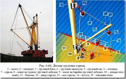
Load booms. Load booms are divided into light and heavy. A light boom is a boom with a lifting capacity of no more than 10 tons, and a heavy boom is a single boom with a lifting capacity of more than 10 tons.
A light cargo boom is a steel pipe with a thickening in the middle part (Fig. 6.64). The lower end of the boom (spur) has a fork with two eyes. A ring (yoke) with four butts is attached to the upper end of the arrow (nock). Arrows of a welded structure may not have a yoke, and to attach the rigging to the end of the arrow, butts are welded.

To articulate the boom spur with the mast, a shoe with an eye and a thrust bearing is installed on the latter at a height of 2 - 2.5 m from the deck.
The arrow's tip is supported by a topenant. By changing the length of the topper, you can change the angle of the boom. The topenant consists of a steel cable, the root end of which is attached to the upper butt of the bow yoke. The second, running end of the topper passes through the topend block mounted on the mast. Below the block, a triangular link is attached to the topenant - the topenant triangle. On the other side, a long-link chain is attached to the triangle - a load stopper and a steel cable - a topenant lever. The topenant lopar is used to lift the boom. The lopar is selected using a cargo winch,
on which the running end of the Lapp is placed. The boom is secured in the desired position with a load stopper, for which one of the chain links is attached to a butt welded on the deck.
On many ships, instead of a cargo stopper, to fasten the topliner and lift the boom, they use topliner views, which are driven into rotation by a cargo winch. To lift booms with cargo, ships have special topping winches or cargo winches are equipped with a topping drum. In this case, the topenant is made in the form of hoists (topenant hoists), which reduces
load on the topping winch. The load is lifted with a flexible steel cable - a cargo pendant. At one end it is secured with a cargo hook (Fig. 6.65 a) and a counterweight, and the other end is led through the cargo and guide blocks to the cargo winch, where it is firmly secured to the drum. 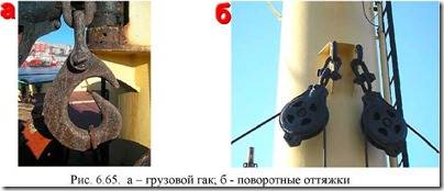 The boom is rotated to carry the load overboard and back using guy ropes (Fig. 6.65 b). Each arrow has two guys, which makes it possible to securely secure it in the desired position. The guy consists of the end of a steel cable - a mantyl and hoists based on a plant cable. The guy ropes are secured to the side butts of the bow yoke, and the hoists with lower blocks are attached to the butts or eyes installed on the deck, bulwark, wheelhouse, etc. When lifting a load, the cargo pendant is selected using cargo winches (Fig. 6.66).
  Light arrows can work both single and paired. When working in a paired version “on the telephone”, the cargo pendants are connected as shown in Fig. 6.67. Then one boom (shore) is installed in the “overboard” position so that its tip is above the pier. The second boom (bilge) is installed in the “above the hatch” position so that its end is above the clearance of the cargo hold hatch (Fig. 6.68).

Unloading is carried out in the following way. The load, hooked to the cargo hook of the “bilge” boom, rises above the hold coaming and bulwarks. The winch of the “shore” boom picks up the slack of its cargo pendant and, as it were, “takes the load upon itself”, at the same time the winch of the “bilge” boom picks up its cargo pendant. The cargo begins to move towards the pier and, as soon as
will be above the unloading site, both pendants are released and the cargo is lowered onto the pier.
The lifting capacity when working on a “telephone” is reduced by almost half relative to the lifting capacity of each individual boom due to an increase in the forces in the booms, pendants and guys, especially when the angle between the pendants is 1200 or more. The disadvantage of this method is that changing the location of lifting or stowing the cargo in the hold requires rearranging the booms, which takes time.

The full lifting capacity of the booms can be used when working using the “single boom” method. In this case, the boom is installed above the hatch and the load on the pendant is lifted from the hold to a sufficient height. Then the boom is thrown overboard using guy ropes and the load is lowered onto the pier. Having picked up the pendant, the arrow is returned to its original position.
The “single boom” method has low productivity and requires a lot of manual labor. Therefore it is applied only in exceptional cases.
At the transition, light arrows are lowered to a horizontal position, for which racks with overhead yokes are installed, in which the ends of the arrows are secured.
Many universal cargo ships are equipped with one or two heavy booms with a lifting capacity of up to 40 - 50 tons, and in some cases (on special ships) - up to 300 tons.
Heavy arrows are used using the single arrow method (Fig. 6.69). 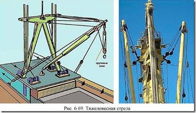 But unlike light booms, heavy-weight booms have three working movements: lifting the load, swinging the boom, and changing the tilt of the boom. The design and armament of a heavy boom have some peculiarities. To reduce the bending of the mast, the boom spur does not rest on the mast, but on a special foundation installed on the deck. The difference in the design of the arrow nock is the presence of a mortise block installed in a slot, which is made slightly below the yoke.
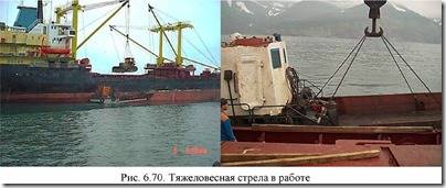 The upper fixed block of multi-pulley hoists - cargo guineas - is suspended from the lower bracket at the end of the boom. A two-horned hook with swivels is suspended from the lower movable block of guineas (Fig. 6.70).
The reloading of heavyweights by ship's means must be carried out under the personal supervision of the chief mate. Only specially trained crew members, announced by order of the vessel, are allowed to work on heavy booms.
Cargo cranes. Cargo cranes are installed on many cargo and passenger ships (Fig. 6.71). The lifting capacity of ship cargo cranes ranges from 1.5 to 25 tons. Cranes installed on ships can be stationary rotary, moving rotary and bridge cranes with a retractable console. The main advantages of cranes compared to twin load booms are their relatively small size, speed of action, constant readiness for action, the ability to rotate the boom with a load 360 degrees and ease of maintenance. The disadvantages of ship cargo cranes include limited lifting capacity and “sensitivity” to roll.

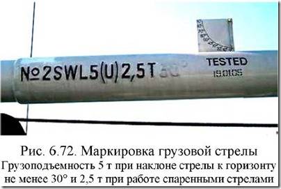
Marking of cargo booms and cranes. Each inspected cargo device must be marked with a stamp containing the following information (Fig. 6.72, 6.73):
– lifting capacity in tons, preceded by the letters SWL (Safety Weight Load), also for booms the smallest permissible angle of inclination to the horizon, and for cranes and mechanized booms with variable reach – the permissible minimum and maximum reach for each installed load capacity;
– month and year of testing;
- distinctive number.

Load capacity is the maximum weight of a load that can be lifted, including the weight of auxiliary devices used to secure the load.
Reach is the distance between the center of gravity of the lifted load and the vertical axis of rotation (for a boom, the spur of the boom).Hatch covers. Cargo hatch closures are divided into removable, roll-away, fold-out and roll-up. To access the holds, large cutouts are made in the decks - cargo hatches, which are fenced around the perimeter with a vertical sheet - coaming 500 - 600 mm high.
The simplest is a removable closure, consisting of a single steel cover that covers the entire hatch. Lifting the covers and installing them in place is done by a crane. The removed cover is placed on the deck or on an adjacent hatch. The most widely used removable covers are used on container ships and lighter carriers, where they can be carried out without hatch coamings, which ensures convenient placement of containers on deck.
 Hinged closure can be made of one cover that covers the entire hatch (Fig. 6.74). The cover is hinged to the coaming and, when the hatch is open, occupies a vertical position, which creates some inconvenience during cargo operations.
Therefore, a hinged closure with two covers is more often used, each of which covers only half of the hatch. The lid consists of two parts - sections, hingedly connected to each other. A powerful hydraulic drive is used to open and close the lids.
The McGregor system, in which the hatch is closed with several metal sections spanning the entire width of the hatch, has been widely used in the navy (Fig. 6.75).
In the traveling position, the sections are tightly compressed. Therefore, before opening the hatch, it is necessary to slightly lift (undermine) the sections, otherwise, when the section moves horizontally, rapid wear of the rubber seal will occur. There are a number of different designs available for raising and lowering sections.  Each of these sections has four drive rollers (two on each side) and two guides (centering). When selecting the cable, which is attached to the last section, all sections begin to move along the hatch, moving on driving rollers along the longitudinal coamings. As the sections successively approach the end of the hatch, the centering rollers roll onto the guide beams and, under the influence of gravity, each section rotates into a vertical position.
Close the hatch in the reverse order. To do this, the leading cable is passed through a rosin block installed at the opposite end of the hatch. When the cable is tensioned, the outer section leaves the guide beams and begins to move along the longitudinal coamings. All sections are connected to each other by a chain, so each section pulls the next one.
The watertightness of the closure is ensured by a rubber seal between the cover and the coaming, as well as between the individual sections of the cover. To tightly compress the rubber seal, the sections are pressed one against the other using wedge clamps. The section is pressed against the hatch coaming with screw locks or wedges.
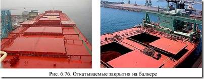
The roll-back closure (Fig. 6.76) consists of two sections, which, when the hatch is opened, roll on rollers to the sides along special guides. With a multi-tier design, the roll-away closure is also made of two sections, each of which can be raised using hydraulic jacks so that the second rolls under it, opening half of the hatch.
Safety precautions when working with a cargo device. Cargo operations belong to the category of high-risk work. The chief mate, chief engineer, boatswain, 4th engineer and electrician are responsible for the technical condition and maintenance of the cargo device.
1. The places where the traction cables pass must be fenced off and the inscription “Passage closed” must be posted. It is prohibited to walk on the hatch sections during their opening, closing, or partial opening.
2. Sections installed in a vertical position must be securely locked. Do not leave them unlocked, even for a short time. Any work in the space between the open hatch sections can only be carried out with the permission of the watch officer or the work manager. During the entire period of work between the sections, there must be a sailor on deck who is obliged to ensure that no one removes the stoppers from the hatch sections, connects the traction cables to the sections, or turns on the hydraulically driven hatch cover control system.
3. It is prohibited to carry out any work on hatch sections that are not completely closed until a temporary railing is installed to prevent people from falling into the hold. The deck in areas where reloading operations are carried out must be fenced off with handrails with posted prohibiting signs on the side towards which the cargo is moving.
4. You cannot go down into unlit and unventilated holds. Lighting chandeliers suspended on rods can be moved only when tension is removed and after all people have left the hold.
5. Persons involved in cargo operations undergo safety training before starting work. First class sailors and other crew members who have undergone special training and have special certificates are allowed to work on lifting mechanisms as a crane operator and winch operator, as well as as a slinger.
6. Only specially trained crew members at least 18 years old, whose names are announced by order of the ship after passing the exam, are allowed to work on heavy-duty devices. Only experienced first class sailors can be appointed as signalmen.
7. The winch operator or crane operator carries out all signals given only by the signalman, except for the emergency stop signal, which must be carried out regardless of who and in what way it is given. Any misunderstood signal should be taken as a stop signal.
The signal for lifting a load can only be given after the slinger has confirmed that the load has been properly lashed and the signalman is satisfied that the movement does not endanger people working in the hold or on deck.
8. It is prohibited to stand or pass under a raised load, to be on the line of movement of the load, under the boom, in the hatch opening, as well as to go down into or out of the hold when lifting and lowering the load. Unauthorized persons are not allowed on the work site during cargo operations.
9. When working on winches and cranes, it is prohibited:
- allow uneven tension of all branches when lifting a load using multi-branch slings;
- adjust the slings when the load is suspended;
- unfasten the load before it is firmly placed on the pads;
- swing the load to place it outside the range of the booms or crane;
- lift a load with people or loose objects on it, as well as a load that is in an unstable position or loaded with other loads;
- pull back, turn around and stop a swinging load while lifting, moving or lowering without using special guys.
10. In addition, when working on winches and cranes it is prohibited:
– deliver cargo into the hold without a warning shout or signal if there are people in the hold;
– supply cargo into the hold before the previously supplied cargo is removed from the hatch opening and people move to a safe place;
– carry cargo at a height of less than 0.5 m from ship structures or objects located in the path of cargo movement;
– leave the load hanging at the end of work or during a break;
– leave live mechanisms unattended;
– adjust the pendant by hand, wind it alone or wind it onto the winch drum during its operation.
11. The operation of the lifting device must be stopped in cases of failure of the correct operation of the brakes, abnormal noise in the mechanism, damage to the cable, malfunction of switches and systematic operation of electrical protection systems.
12. When transporting cargo on deck, the following basic requirements must be met:
– deck cargo must be stowed in such a way that there are safe passages for people with a width of at least 0.7 m from all rooms to ladders, measuring and air pipes, fire stations, horns and fire extinguishers, etc.;
– all passages must be through (without dead ends);
– the fastening of the deck cargo must be done reliably, but with the calculation that in a critical position of the ship it is possible to quickly release the lashings or, in extreme cases, cut them.
13. When handling dangerous and flammable goods, in addition to the above, you should also be guided by the transportation rules established for them.
14. When crossing by sea, the parts of the cargo device must be securely fastened in a traveling manner:
– the ends of the arrows are well fixed in the nests;
– the hooks of the cargo pendants are laid behind the deck eyes (toes up with capping), and the cargo pendants are tightly tightened on the winch drums;
the lower blocks of guys are laid out from the eyes and laid at the spur of their boom, the hoist flaps are tightened, laid in a coil and suspended from the mast;
the cargo pendant and the slings of the guy hoists are secured to the boom in several places by lines.


Ship lifting devices must have the following documents:
register book of ship lifting devices;
certificates of testing and full inspection of lifting devices, twin load arms, replaceable and removable parts, steel cable:
manufacturer certificates for vegetable and synthetic cables;
Instructions for operating twin booms and cranes.
Rice. 3.4.9. Marking: a) – cargo boom; b) – cargo crane
Each inspected cargo device must be affixed with a stamp containing the following information:
Load capacity, t, with the letters SWL (Safety Weight Load) placed in front of it, for booms also the smallest permissible angle of inclination to the horizon, and for cranes and mechanized booms with variable reach - the permissible minimum and maximum reach for each installed load capacity;
Month and year of test;
Distinctive number.
| Marking sign | Meaning of the sign |
| Arrows | |
| SWL 1.5 t 15° | Load capacity 1.5 t when the boom is tilted to the horizontal at least 15° |
| SWL 5 t 30° | Load capacity 5 t when the boom is tilted to the horizontal at least 30° |
| SWL 3-5 t 15° | |
| SWL 3-5 t 30° | When the boom is tilted to the horizon at least 30°, the load capacity is 3 tons with a single pendant and 5 tons with a double pendant base (hoist) |
| SWL 3-5 t 15° | When the boom is tilted to the horizon at least 15°, the load capacity is 3 tons with a single pendant and 5 tons with a double pendant base (hoist) |
| SWL 10 t 30° | When the boom is tilted to the horizon at least 30° when using special boom armament in accordance with the device documentation, the load capacity is 10 tons |
| SWL 80 t 25° | Load capacity 80 t when the boom is tilted to the horizontal at least 25° |
| SWL3t2t15° | Load capacity 3 t when the boom is tilted to the horizontal at least 15° |
| V | Load capacity 2 t when working with twin booms in accordance with the instructions for arming and exhuming twin booms |
| Cranes | |
| SWL3T | Load capacity 3 t (for non-boom cranes and hoists, as well as cranes with a fixed boom) |
| SWL1.5t4-12m | Load capacity 1.5 t with boom radius from 4 to 12 m |
| SWL3T4-12M | Load capacity 3 t with boom radius from 4 to 12 m |
Load capacity is the maximum weight of a load that can be lifted, including the weight of auxiliary devices used to secure the load.
Reach is the distance between the center of gravity of the lifted load and the vertical axis of rotation (for a boom, the spur of the boom).
Hatch covers
To access the holds, large cutouts are made in the decks - cargo hatches, which are fenced around the perimeter with a vertical sheet - coamings height 500 - 600 mm.
Cargo hatch closures are divided into removable, roll-away, fold-out and roll-up.
The simplest is removable closure, consisting of one steel cover that covers the entire hatch. Lifting the covers and installing them in place is done by a crane. The removed cover is placed on the deck or on an adjacent hatch. The most widely used removable covers are used on container ships and lighter carriers, where they can be carried out without hatch coamings, which ensures convenient placement of containers on deck.

Rice. 3.4.10. Folding hatch cover with hydraulic drive:
1 – leading section; 2 – driven section; 3 – socket for the locking strip; 4 - roller of the driven section; 5 – limiting post; 6 – racks; 7 – plunger; 8 - rubber shock absorbers; 9 – extreme brackets
Hinged closure can be made of one cover that covers the entire hatch. The cover is hinged to the coaming and, when the hatch is open, occupies a vertical position, which creates some inconvenience during cargo operations. Therefore, a hinged closure with two covers is more often used, each of which covers only half of the hatch. The lid consists of two parts - sections, hingedly connected to each other. A powerful hydraulic drive is used to open and close the lids.
Closures are widely used in the navy McGregor systems, in which the hatch is closed with several metal sections spanning the entire width of the hatch.
In the traveling position, the sections are tightly compressed. Therefore, before opening the hatch, it is necessary to slightly lift (undermine) the sections, otherwise, when the section moves horizontally, rapid wear of the rubber seal will occur. There are a number of different designs available for raising and lowering sections.

Rice. 3.4.11. Hatch closure of the McGregor system:
1 – hatch section; 2 – guide beam; 3 – centering roller; 4 – support rollers; 5 – chain connecting the sections to each other; 6 - connecting wedge; 7 – cable intended for opening; 8 – cable intended for closing; 9 – rosin block
Each of these sections has four drive rollers (two on each side) and two guides (centering). When selecting the cable, which is attached to the last section, all sections begin to move along the hatch, moving on driving rollers along the longitudinal coamings. As the sections successively approach the end of the hatch, the centering rollers roll onto the guide beams and, under the influence of gravity, each section rotates into a vertical position.

Close the hatch in the reverse order. To do this, the leading cable is passed through a rosin block installed at the opposite end of the hatch. When the cable is tensioned, the outer section leaves the guide beams and begins to move along the longitudinal coamings. All sections are connected to each other by a chain, so each section pulls the next one.
The watertightness of the closure is ensured by a rubber seal between the cover and the coaming, as well as between the individual sections of the cover. To tightly compress the rubber seal, the sections are pressed one against the other using wedge clamps. The section is pressed against the hatch coaming with screw locks or wedges. This hatch cover system is reliable, durable and waterproof.

Rice. 3.5.12. Retractable closures on a bulk carrier
Roll-back closure consists of two sections, which, when the hatch is opened, roll on rollers to the sides along special guides. With a multi-tier design, the roll-away closure is also made of two sections, each of which can be raised using hydraulic jacks so that the second rolls under it, opening half of the hatch.
Boom reach and crane capacity indicators
On cranes with luffing jib, in which the lifting capacity varies depending on the boom reach, boom reach and load capacity indicators are installed. For example, cranes BK-2, T-72, T-178 are equipped with such indicators, in which the boom radius is changed with a load using an electric winch.
The diagram of the boom reach indicator and the load capacity of the BK-2 crane is shown in Fig. 80.
The pointer is a metal sector mounted on the rotating head of the crane. The sector is connected to the head using bolts. It contains divisions corresponding to the largest, smallest and several intermediate boom extensions. Under each of these divisions the value of the permissible lifting capacity of the crane at a given boom radius is indicated. The numbers on the scale indicating the load capacity are made as large as possible so that they are visible not only to the driver, but also to lower-level riggers. For the same purpose, the sector is usually painted white, and the numbers for the load capacity and boom reach are made black or red.
Reach and load capacity indicators allow the driver and riggers to determine the possible permissible load capacity at a given reach and thereby load the crane as fully as possible in accordance with this characteristic.
The presence of limiters on the crane for hook lifting height and lifting capacity does not preclude the installation of appropriate indicators. In the event of a temporary malfunction of the load limiter, which was not detected by the operator, the absence of a load indicator can lead to overloading of the crane, breakage of its individual elements, and even its fall.

Rice. 80- Indicator of boom reach and lifting capacity of the BK-2 crane.
13. MARKING OF ELEMENTS OF CARGO DEVICES
All replaceable and removable parts after testing with a test load and with a positive inspection result must be marked and branded. In this case, the following data must be entered:
Load weight corresponding to maximum working load SWL;
Month and year of testing;
Distinctive part number;
The Register's mark or the manufacturer's mark.
Own weight with the presence of TW (t) in front of it (for lifting devices - lifting beams, frames and spreaders).
Table1 3 . 1
Examples of part markings


Each lifting device (cranes, booms, winches, views), tested with a test load and with positive survey results after the test, must be given a stamp containing the following data:
load capacity, t, with front lettering SWL; for booms the smallest permissible angle of inclination to the horizon, and for cranes and mechanized booms with variable reach - the maximum and minimum permissible reach; with a variable load capacity depending on the boom reach - the smallest and largest reach for each installed load capacity; for passenger elevators – the allowed number of passengers;
month and year of testing;
distinctive number;
Register stamp. The mark should be applied on the boom spur fork, and for jib cranes - on the lower end of the boom near the support.
The numbering of cargo devices on a ship is carried out in the following order:
All light and heavy booms not located in the centerline of the vessel - from starboard to port;
Cargo cranes, regardless of cargo booms, starting from the bow from starboard to port.
Examples of designation of cargo booms and cranes.
|
Marking sign |
Decoding the sign |
|
Arrows |
|
|
SWL 1,5 t 15 |
Load capacity 1.5 t when the boom is tilted to the horizon at least 15 |
|
SWL 5 t 30 |
Load capacity 5 t when the boom is tilted to the horizon at least 30 |
|
SWL 3- 5 t 15 |
When the boom is tilted to the horizon at 15°, the load capacity with a single pendant is 3 t and 5 t with a load hoist |
|
SWL 20 t 25 |
Load capacity 20 t when the boom is tilted to the horizon at least 25 |
|
SWL 3 t 2 t 15 |
Load capacity 3 t when the boom is tilted to the horizon at least 15 Load capacity 2 t when working with twin booms |
|
Cranes |
|
|
SWL 3 T |
Load capacity 3 t (for non-boom cranes and fixed reach lifts) |
|
SWL 1,5 t 4-12 m |
Load capacity 1.5 t with boom radius from 4 to 12 m |
|
SWL 5 t 4-6 m |
Load capacity 5 t with boom radius from 4 to 6 m |
|
SWL 32/8 t – 22/24 m |
Load capacity 32 t when the main lifting mechanism is working, when the auxiliary lifting mechanism is working 8 t The maximum reach of the main hook is 22 m, and the maximum reach of the auxiliary hook is 24 m. |
|
SWL
|
Load capacity 100 t with a boom radius of 16 m and 32 t with a boom radius of 24 m |

1 4 . SAFETY DEVICES
Safety devices are designed to ensure trouble-free operation of lifting machines. They ensure timely stopping of mechanisms and prevent the occurrence of loads that are dangerous for the elements of mechanisms. Based on their operating principle they are divided into:
a) safety ones, which, when triggered, ensure that the mechanism stops;
b) alarms, giving a sound or light signal warning of reaching a dangerous position or the appearance of a dangerous load.
According to their purpose, safety devices are classified into the following groups:
limit switches designed to limit the path of cargo movement (load lifting height limiters), boom movement and crane rotation, sagging cables;
load capacity and load moment limiters protecting the crane from overload;
stops, buffer devices, skew limiters that limit the maximum position of the crane and its elements.
The load lifting height limiter is installed on the boom toe. The lift height limiter for a cargo suspension with a pulley system is shown in Fig. 1 a). The cargo suspension 4, when moving to the upper position, rests against the counterweight 3, the rod 2 of which raises the lever 5 of the limit switch 1, and de-energizes the power to the electric motor.
If the load is suspended without a pulley, then the lifting height limiter shown in Fig. 1 b). The pendant passes through the hole 4 in the load 3, which is suspended on a cable 2. When the cargo suspension is in the uppermost position, its counterweight lifts the load 3 and the cable 2, which moves the limit switch lever 1 to the left and de-energizes the electric motor.

Fig.1. Lift height limiters
To prevent pendants and toppers from falling off blocks and drums when their tension is weakened, cable sag limiters are used, the diagram of which is shown in Fig. 2. If the tension of the cable 1 weakens, the L-shaped lever with rollers 3 under the action of the counterweight 4 will move to the right and press the limit switch, which will de-energize the electric motor.

Fig.2. Scheme cable slack limiter
The load limiter is designed to prevent overloading of the crane, which can lead to breakage of flexible cargo traction elements (cables and chains), breakage of hooks and other parts of the mechanism, formation of cracks and residual deformations of the metal structure. The load limiter automatically turns off the hoist motor when lifting a load whose weight exceeds the rated load capacity by more than 10%. The diagram of the spring load limiter is shown in Fig. 3.

Fig.3. Scheme load limiter devices
Block 1 is placed on lever 2. The block mount is shifted by the amount of eccentricity e relative to the axis of its displacement. The other end of the lever is supported by spring 3. The lever will be in equilibrium under the condition
 ,
,
Where F shk – pendant tension,
e – eccentricity,
F etc – spring elastic force,
L p – lever length.
When lifting a load whose mass exceeds 10%, lever 2 lowers, overcoming the elasticity of the spring, closes limit switch 4 and de-energizes the electric motor.
Ship cranes equipped with a hydraulic drive are equipped with a safety valve as a load limiter.


